1.Hybrid Simulation Tests of the Steel Specimen at Various Earthquake Intensities
This is a continuation of the hybrid tests of the steel frame prototype already tested for low intensities and linear range. Both the Test Setup 1, for Conventional Substructuring Technique (CS), and Test Setup 2, for Pinned Substructuring Technique (PS), are going to be subjected to increasing intensities of 20%, 40%, 60%, and 100% of the Canoga Park ground motion. The results of these tests will be analyzed and compared with the Finite Element Analysis (FEA) of the prototype.
2. Hybrid Simulation For Concrete Specimens – Application of Control and Reparability of Damage (CARD)
The purpose and objectives of the ExDSR is to conduct state-of-the-art-research on the facilities. This next project under development involves the HS of a concrete column part of a nuclear power plant frame which is an analytical research project conducted by Dra. Aidcer Vidot from the Department of Engineering Sciences and Materials also awarded a Faculty Development Award from the Nuclear Regulatory Commission (NRC). We want to verify her findings with a HS of a concrete column of the frame. However, our main objective is to test walls.
For the experimental part, we wanted to have a test-setup were there could be repeatability of tests while using the least number of specimens. Cheng and Mander (1997) developed on their report “Seismic Design of Bridge Columns Based on Control and Reparability of Damage” the Control ad Reparability of Damage (CARD) concept.
CARD design approach by Cheng and Mander (1997)
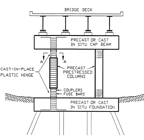
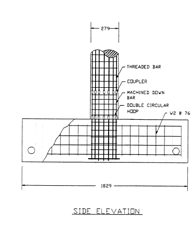
The proposed CARD design method for concrete columns of bridges aimed to quickly repair a structure post-earthquake to maintain serviceability. The concept was based on the typical failure of these columns: (1) failure of the concrete due to either lack of confinement or the fracture of the transverse hoop reinforcement and /or (2) compression buckling of the longitudinal reinforcement. These failures can be avoided utilizing appropriate transverse reinforcement. This leaves low-cycle fatigue of the longitudinal reinforcement as the remaining failure mode. This low-cycle fatigue on the longitudinal reinforcement lead to replaceable plastic hinge concept, using threaded couplers as means of separating the damaged and the undamaged part of the longitudinal reinforcement. By placing this couplers at the plastic hinge zones, these damage parts can be replaced after a seismic event. These plastic hinge zones should be properly placed to ensure that damage can be limited and controlled entirely within the plastic hinge regions. The CARD approach uses this weakened/relocation concept, but also makes the hinge zone a “sacrificial fuse” that is repairable. This can be achieved by machining down the longitudinal reinforcement to smaller diameter. Figure 1 (a) shows where the couplers would be placed, and Figure 1(b) shows a section of the plastic hinge zone.
Application to HS of Concrete Columns
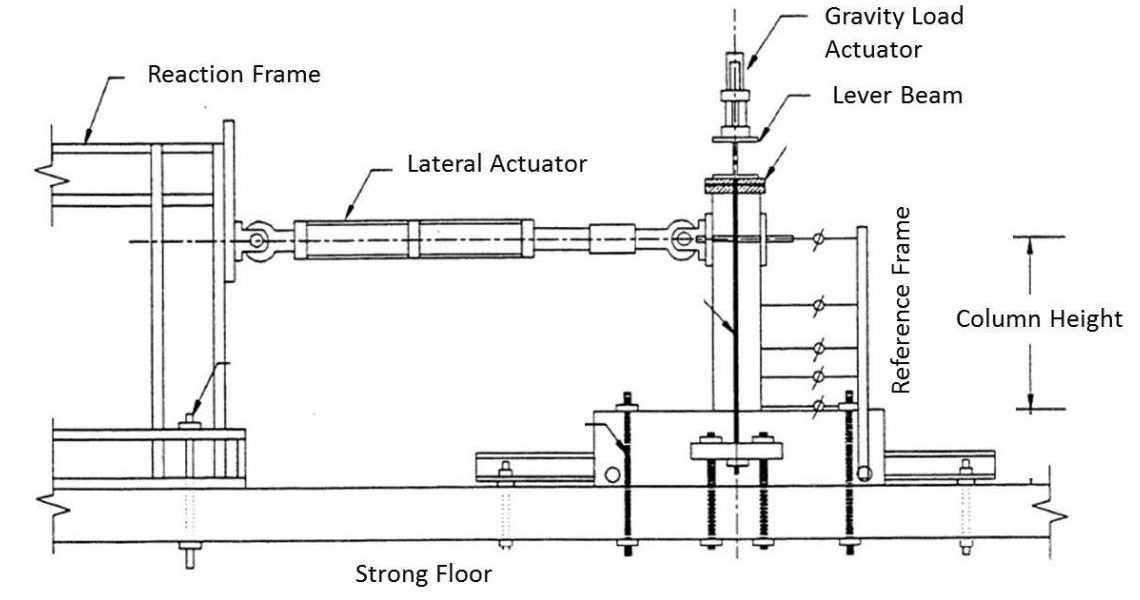
We will use this procedure to locate the plastic hinge zone and quickly repair after testing for repeatability of tests. Figure 3 shows the setup design by Cheng and Mander to test their concept. We are modifying this setup to accommodate for our test objectives and our laboratory.


