The components of the UPRM hybrid simulation facility are mentioned below.
1. Servo-controller
The components of the UPRM hybrid simulation facility are mentioned below.
1. Servo-controller

a) b)
Figure 1 FlexTest-60 Servo-controller: a) front view; b) back view. [4]
The MTS FlexTest-60 Servo-controller consists of a one Model 494.06 Chassis that contains controller hardware and a computer workstation that runs MTS controller applications. The Servo-controller uses Series 793 Software to operate the hydraulic system and it is run by the Control computer. The system control is provided by a fully digital proportional, integral, derivative, feed forward (PIDF) Servo-controller algorithm.
2. Hydraulic Power Unit

a) HPU front view. b) HPU back view.
Figure 2 Hydraulic Power Unit. [4]
Hydraulic Power Unit (HPU) is the main component of the hydraulic power system. The HPU supply the system with the hydraulic fluid through the hydraulic hoses. There are two main line of hoses, pressure and return lines. The pressure line transport the fluid from the HPU to the Hydraulic Service Manifold (HSM), and from the HSM to the hydraulic actuators. The return line transmits the fluid in the opposite direction, from the hydraulic actuators to the HSM, and from the HSM to the HPU. The HPU distributes the fluid with an operation pressure of 3,000 psi at a flow rate of 70 gpm. It has a maximum capacity of 200 gal of hydraulic fluid and works at a normal temperature of 110 °F.
3. Radiator Cooling System
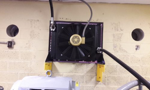
Figure 3 Radiator cooling system. [4]
The hydraulic fluid is cooled by a radiator system. Some amount of fluid is constantly conveyed from the HPU to the radiator. The radiator produces an air flow that cools the fluid passing through it. This process keeps the fluid in the HPU tank at the adequate temperature.
4. Hydraulic Service Manifold

a) HSM front view. b) HSM back view.
Figure 4 Hydraulic Service Manifold. [4]
The Hydraulic Service Manifold (HSM) is the component that provides the line pressure regulation. The HSM distributes the hydraulic fluid from the HPU to the hydraulic actuators. In addition, it returns the fluid used by the actuators back to the HPU. Its control is independent from the HPU´s control. The HSM contains a pressure accumulator which reduces pressure and flow fluctuation as a result of changes in system demands, especially during peak flow. It has two channels, each one associated with one actuator and servovalve.
5. Hydraulic Actuator
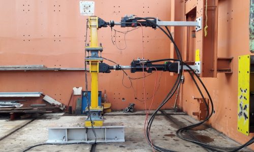
Figure 5 Hydraulic actuators. [4]
A hydraulic actuator consists of a cylinder that contains a piston that can extend or retract (double-acting). Its function is to apply a displacement or force to an experimental specimen for testing. The piston is moved when the hydraulic fluid is supplied at high pressure to one actuator’s chamber while the other chamber allows the fluid to come out through the return line. Inside the piston rod there is a linear variable differential transformer (LVDT) that measures displacement. The actuator also has a load cell transducer at the end of the rod to measure force. Two Series 244 MTS actuators were used in this research, shown in Figure 5. The force capacity and stroke is 22 kip, ± 3 in for the 244.22 model, and 50 kip, ± 5 in for the 244.31 model.
6. Actuator Servovalve
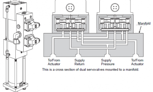
The most important part of the hydraulic actuator is the servovalve, which is the final control element in most MTS close-loop systems. The servovalve regulates the direction and flow of the fluid received from the HSM. The fluid enters through the pressure port and then is directed to the different chambers, the difference in pressure cause the movement of the piston rod. Both actuators have a MTS Series 252 dual servovalve mounted to a manifold as shows Figure 6.
7. Reaction System
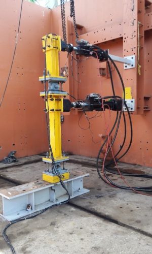
The hybrid simulation facility, as well as other experimental test methods, needs a reaction system to resist the forces applied during the test and to prevent undesirable movement of the test specimen or test setup. Figure 7 shows the reaction system of the Structures Laboratory which consists of a steel reaction frame and a concrete strong floor. The two actuators used in this research are connected to the reaction frame, which has a capacity of 200 kip/ft2, while the test setup foundation is fixed to the Laboratory strong floor.
8. Computer Workstation And Software
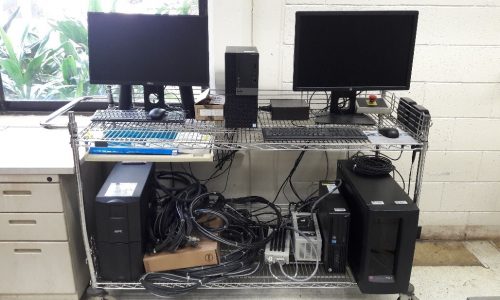
Figure 8 Computer workstation. [4]
The MTS application to control the Servo-controller is managed by a Control Computer. The MTS application that runs the Servo-controller is Series 793 Software. By means of the Control Computer, the Servo-controller sends the signal to turn on the HPU and HSM, and send the displacement command signal to the actuator’s servovalve. The Control Computer runs the software OpenSees and OpenFresco to analyze the numerical substructure of the hybrid simulation. The displacements measured by the actuator’s LVDT and the forces measured by the load cell are transmitted to the Control Computer to apply them in the analysis.
OpenSees, the Open System for Earthquake Engineering Simulation, is a software used to simulate the performance of structures subjected to earthquakes. It is an open-source software so users can incorporate changes to the program in accordance with their needs. For this reason, the software is under continual development. OpenFresco, the Open-source Framework for Experimental Setup and Control, is an environment-independent software framework used in hybrid simulation to establish communication between finite element models and control and data acquisition systems.