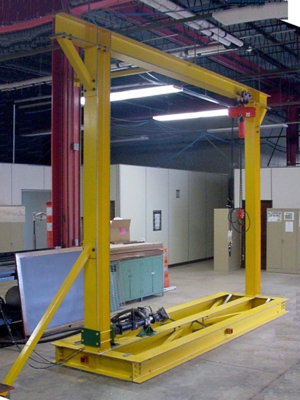
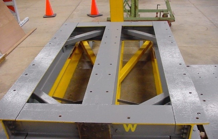
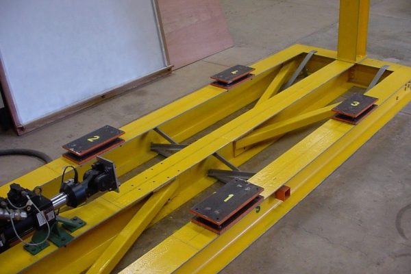
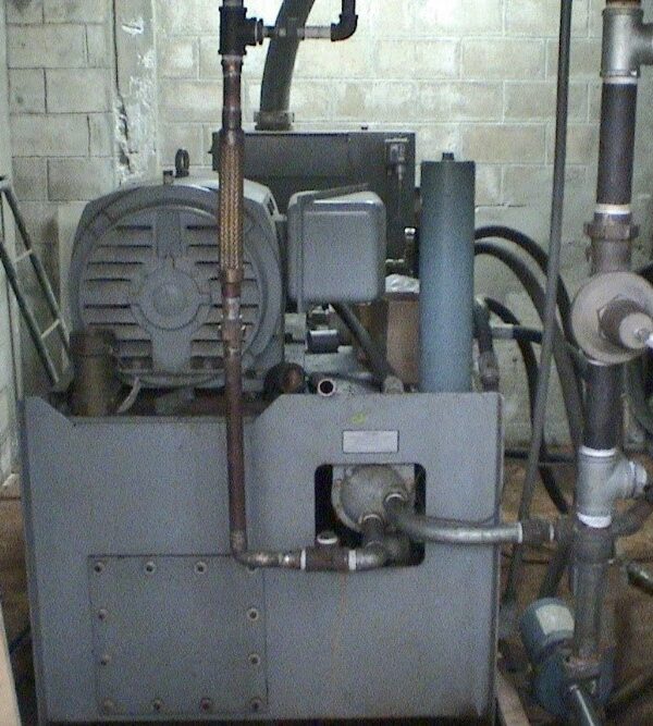
Figure 4. UPRM MTS 506.61 Hydraulic Power Unit.
The Hydraulic Power Supply (pump) installed in the laboratory is a MTS Model 506.61 and is rated at 265.0 l/min (70 gpm) of steady flow [24]. A Hydraulic Service Manifold (HSM) MTS Model 293.11, with a rated capacity of 190.0 l/min (50 gpm), is mounted between the HPS and the servovalves.
5. Hydraulic Service Manifold
Service Manifolds provide hydraulic accumulation and filtering functions for individual actuators in a system. Hydraulic hoses provide connection of components within the hydraulic power distribution on system. Figure 5 shows the HSM which distributes the hydraulic fluid from the HPU to the actuator.
Figure 5. UPRM MTS 293.11. Hydraulic Service Manifold.
6. Servovalve and Actuator
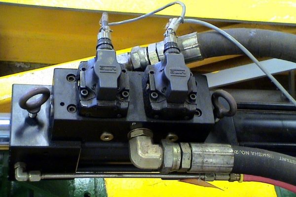
The servovalve shown in Figure 6 provides the final control element in a closed loop servo-hydraulic system. The servovalve ports the fluid, provided by the hydraulic power system, into the appropriate side of the actuator’s chambers. This causes the actuator’s piston to move the actuator’s arm in the desired direction.
Figure 6. MTS 252.25 Dual Servo-valves.
The servovalves, dual MTS Model 252.25 two-stage servovalves, are rated at 56.0 l/min (15gpm) each for a total of 112.0 l/min (30gpm) maximum flow.
7. Linear Hydraulic Actuator
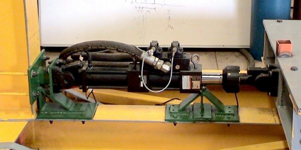
The linear actuator consists of a cylinder that contains a piston. The LVDT, which measures displacement, is inside the piston rod. The linear actuator system also consists of a load cell transducer, which measures force. Figure 7 shows the linear hydraulic actuator.
Figure 7. MTS 244.11 linear hydraulic actuator.
The movement of the actuator piston rod is accomplished by supplying high pressure hydraulic fluid to one side of the actuator piston (actuator’s chamber) and opening the other side to the return line. The force rating of a linear actuator is equal to the effective piston area times the actuating pressure. The maximum flow rate available
also determines the maximum simulator platform velocity. The load cell is connected at the end of the actuator’s piston rod and in turn to a swivel mounting head. The swivel head connects the actuator-load cell system to the simulator platform, as illustrated in Figure 7.
The actuator MTS Model 244.21 Hydraulic actuator is rated at 48.93 kN (11 kips) and with an effective area of 25.16 cm2 (3.90 in2) and a stroke of ±7.62 cm (± 3.00 inches).
8. Servo Controller
The MTS FlexTest-60 Servo-controller consists of a one Model 494.06 Chassis that contains controller hardware and a computer workstation that runs MTS controller applications. The Servo-controller uses Series 793 Software to operate and the software is run by the Control computer. The system control is provided by a fully digital proportional, integral, derivative, feed forward (PIDF) Servo-controller algorithm.
I am text block. Click edit button to change this text. Lorem ipsum dolor sit amet, consectetur adipiscing elit. Ut elit tellus, luctus nec ullamcorper mattis, pulvinar dapibus leo.
a) front view b) back view.
Figure 8. MTS FlexTest-60 Servo-controller
